Introduction to Networking
Posted on / 14 Jan 2018
With the advent of more complex digital technology used within control systems for live events, it is necessary for engineers to have an understanding not just of audio or lighting, but of at least the basic workings of computer systems which are used to drive it.
One of the more common systems used in the live industry revolves around computer networking, Ethernet, and (in some cases) the TCP/IP stack. This post is a primer for technicians with no prior knowledge of computer networking. It’s worth noting that I am making a few broad generalisations in the course of this post, sacrificing complete accuracy for ease of understanding.
Physical
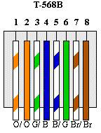
Let’s begin with the interconnections. All computer networking connections that we’re likely to encounter will use Cat5 (Category 5) cable. There are a number of other categories of cabling (most notably Cat5e ‘enhanced’ and Cat6, which are manufactured to lower tolerances regarding crosstalk and noise, allowing higher transmission speeds), but for most uses Cat5 is sufficient. At the device ends, our Cat5 cable is terminated with an RJ45 plug, which is an 8 pin latching connector. There are two standards for which of the 8 conductors in a Cat5 cable go to which connector, which are specified in TIA/EIA-568 T568A and TIA/EIA-568 T568B. You’re free to use either, but the ~B standard is more common. The important factor is that the connections are consistent in a cable. You are also likely to encounter Neutrik’s Ethercon connection, which encapsulates the standard RJ45 connection within a more rugged XLR-style locking chassis.
There are, additionally, several different types of Cat5 cable – UTP, STP, and FTP being the most common. These denote the internal structure of the cable. It is usually recommended to use FTP or STP cable in your interconnects; while not necessary within the Ethernet standard, the shielding is sometimes used in other applications. For example, d&b audiotechnik use the shield of an ethernet cable to carry the reference ground for CAN bus operation. The maximum recommended length for a single run if Cat5 is 100 meters. It can be longer with good quality hardware and cabling, but there will be an increase in crosstalk and noise along the run, which will give a corresponding drop in throughput.
It’s worth noting additionally that while it is standard for Cat5 cables to be wired as ‘straight through’, which is to say using T568B at both ends, it is sometimes necessary to manufacture a ‘crossover’ cable, most commonly used for connecting two older switches or computers together, which uses T568B at one end, and T568A at the other, ‘crossing over’ the orange and green conductor cables. These are generally unnecessary in a modern situation; computers and switches alike are smart enough to realise what kind of cable they are connected with, and will work things out between themselves without our assistance.
Hardware and the OSI 7 Layer Model
Let’s talk a little about networking hardware. There are, generally speaking, three specialised devices used in computer networking; routers, switches and hubs. Hubs are generally not used in modern networks; they create a shared electrical bus between a number of hosts on a network, with no intelligent management of network traffic at all; every piece of data sent from one computer will arrive at all other computers connected to that hub, whether they need it or not. This slows down a network quite considerably. A hub is a Layer 1 device (more on this later).
Switches are more intelligent hubs; they are capable of looking at network traffic and identifying where a particular piece of data is bound, and sending it only to the port which the destination computer is connected to. Switches can be subdivided into two categories – managed and unmanaged switches. A managed switch allows a user to take greater control of the traffic through the switch, specifying duplex settings, VLANs, port mirroring or trunking, and redundancy options. An unmanaged switch has no configuration options, and are generally sufficient for our purposes. Switches can come as layer 2 or layer 3 devices, and this distinction is important when working with technologies such as Waves SoundGrid, which is a layer 2 protocol.
Routers are where all the fun stuff happens; at their simplest, they allow you to route network traffic between different networks (we’ll talk about this in a little more detail later). Modern routers also have other options built into them – firewalls, VPNs, NAT, port forwarding, and so forth. Some of these are useful to us, most of them are not. Routers are a layer 3 device.
It’s worth taking a little look at OSI’s 7 layer network model. This is a way of grouping the functions of an ethernet communication into logically consistent layers, which build upon each other.
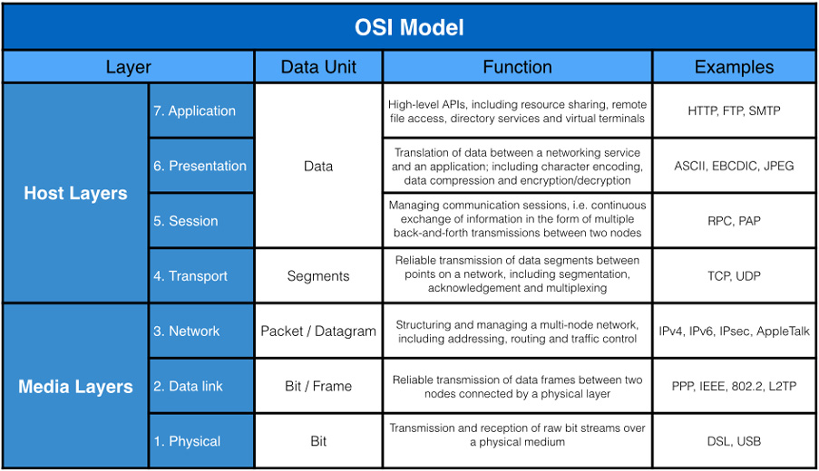
We will generally be concerning ourselves with the bottom three layers – physical, data link, and network. In fact, we’ve already briefly covered one without you realising it. Layer 1 specifies the physical and electronic specifications for our connection; in short, what cables to use, what voltages they should carry, what pins should be used for what purpose, and so on. Faults in layer 1 would generally be things like broken cables, or improperly made connections.
Layer 2 is where things start to get interesting. The Data Link layer defines the rules for when a device can send data over a particular medium (I.e, a network cable), and provides some error correction. This layer concerns itself with MAC addresses, which is a unique identifier for a particular piece of network hardware (every computer network port has its own MAC, for example, as does every router). We generally do not end up with faults in layer 2 unless you are using advanced network systems such as Spanning Tree Protocol. This is very unlikely in a show control system.
Layer 3, the Network layer, concerns itself with addressing, routing, and determining paths through a network. This is where IP addressing happens, and where the majority of our faults will occur, usually due to a misconfiguration of some sort.
IP Addressing and Subnets
An IP address is a way of uniquely identifying a device on a network. An IPv4 address will consist of four one-byte (0-256) values (effectively a 32 bit binary number), commonly arranged as a ‘dotted quad’ or ‘dotted decimal’, for example: 216.58.208.46. Some of these addresses are reserved; most notably 0.0.0.0, 127.0.0.1 and 255.255.255.255. Additionally, three address ranges are reserved for ‘private’ use, which is to say, internal networks. These three address ranges are 10.x.x.x (Class A), 172.16.x.x through to 172.31.0.0 (Class B), and 192.168.0.0 through to 192.168.255.0 (Class C). The last one of these is probably familiar to you.
Because an IP address is used to uniquely identify devices on a network, two devices cannot share an IP address; if they did, devices on the network wouldn’t know where to send data packets.
When looking through the configuration options for your computer, you’ll probably also have noticed an option for a Subnet Mask. A subnet (short for subnetwork) mask allows you to let you (in effect) run several sub-networks within one larger network. For example, a marketing department and a finance department in an office would share the same network, but might not need to see each others’ devices on the network, so you create two subnets; one for marketing, and one for finance. These two subnetworks would each have their own subnet mask.
The intricacies of subnettting are beyond the scope of this article. Suffice it to say, every device on your network should have the same Subnet Mask – in this case of networks starting 192.168, this is usually 255.255.255.0.
When configuring your devices to get them onto your network, there are two overarching methods of assigning IP addresses. The first is to give every device a static IP – you sit down at each device and tell it what its IP address is. This is fine for small networks, but quickly becomes a timesink when dealing with larger networks.
Fortunately, there is a way of automatically assigning IP addresses to devices. This is known as DHCP (Dynamic Host Control Protocol). In simple terms, a DHCP server sits on your network, and every time a new device connects to it (i.e you connect to the wifi, or plug in a cable), the newly-added device sends out a broadcast saying, in plain English, ‘I’m here. What should my IP address be? What are the other details I need to know?’. The DHCP server hears this broadcast, and tells the new device all the details it needs to sit nicely on the network.
DHCP servers are very common – just about every consumer and prosumer router comes with a DHCP server built-in, and computers themselves can be configured to run a DHCP server program.
It’s useful sometimes to be able to have the best of both worlds – knowing exactly the IP address for a particular device, but not having to assign new details to every crew member’s phone, tablet and laptop. In such situations, you can usually edit the settings of your DHCP server (in most cases, this will be your router) so that instead of assigning addresses across the full range 192.168.0.2 through 192.168.2.254, it reserves some addresses. I tend to set things so the DHCP server will assign addresses starting at 192.168.0.100 and ascending, which leaves me with 98 addresses which I can assign to show-critical systems.
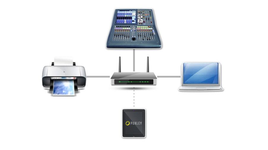
Example network
Subnet mask 255.255.255.0
| 192.168.0.1 | Gateway | ||||
| 192.168.0.70 | System Controller | d&b audiotechnik R70 | |||
| 192.168.0.71 | FOH Desk | Midas Pro6 | |||
| 192.168.0.72 | Monitor Desk | Midas Pro2 | |||
| 192.168.0.73 | Lighting Desk | Chamsys MQ100 | |||
| 192.168.0.74 | Printer | Brother DCP-5055 | |||
| 192.168.0.75 | Network Bridge | Klark Teknik DN9650 | |||
| 192.168.0.100 | DHCP Lease Pool Start | ||||
| 192.168.0.250 | DHCP Lease Pool End |
Any suggestions or corrections, questions or comments? Get in touch.
Ask a Quick Question
"*" indicates required fields
News from our Blog
Gigs and Global Warming
Posted / 1 Dec 2019

Concert Noise Management
Posted / 11 Nov 2019
Knowledge Base Articles
Crew Comms for Festivals and Concerts
Posted / 25 Jan 2019
Introduction to Networking
Posted / 14 Jan 2018
Equipment for Hire
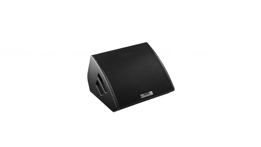
d&b audiotechnik M4 Stage Monitor
£20.00 per day
£60.00 per week
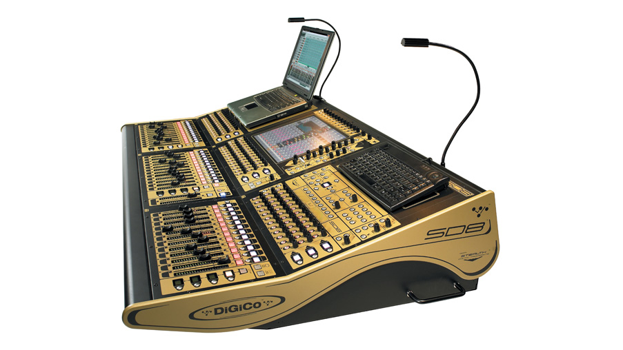
DiGiCo SD8 mixing console
£225.00 per day
£675.00 per week